Operator’s Manual
optris
®
CS
Infrared thermometer

Optris GmbH
Ferdinand-Buisson-Str. 14
13127 Berlin
Germany
Tel.: +49 30 500 197-0
Fax: +49 30 500 197-10
E-mail: info@optris.global
Internet: www.optris.global

Table of contents 3-
Table of contents
Table of contents .............................................................................................................................................. 3
1 General notes ............................................................................................................................................ 7
1.1 Intended use ....................................................................................................................................... 7
1.2 Warranty ............................................................................................................................................. 8
1.3 Scope of delivery ................................................................................................................................ 8
1.4 Maintenance ....................................................................................................................................... 9
2 Technical Data ........................................................................................................................................ 10
2.1 Default settings ................................................................................................................................. 10
2.2 General specifications ...................................................................................................................... 13
2.3 Electrical specifications ..................................................................................................................... 14
2.4 Measurement specifications ............................................................................................................. 16
2.5 Optical charts .................................................................................................................................... 17

-4 -
2.6 Close focus optics ............................................................................................................................. 20
2.7 LED-Functions .................................................................................................................................. 21
2.7.1 Automatic aiming support ......................................................................................................... 21
2.7.2 Self-diagnostic .......................................................................................................................... 22
2.7.3 Temperature code indication .................................................................................................... 23
3 Installation ............................................................................................................................................... 25
3.1 Mechanical Installation ..................................................................................................................... 25
3.1.1 Mounting accessories ............................................................................................................... 26
3.1.2 Air purge collar .......................................................................................................................... 27
3.1.3 Other accessories ..................................................................................................................... 29
3.1.4 Tilt assembly ............................................................................................................................. 30
3.2 Electrical Installation ......................................................................................................................... 31
3.2.1 Digital communication ............................................................................................................... 33

Table of contents 5-
3.2.2 Open collector output ................................................................................................................ 34
3.2.3 Direct connection to a RS232 on the computer ........................................................................ 35
4 Schematic circuit diagrams for maintenance applications ................................................................ 36
5 IRmobile app ........................................................................................................................................... 39
6 Software CompactConnect .................................................................................................................... 41
6.1 Installation ......................................................................................................................................... 41
6.2 Communication settings ................................................................................................................... 43
6.2.1 Serial Interface .......................................................................................................................... 43
6.2.2 Protocol ..................................................................................................................................... 43
7 Basics of Infrared Thermometry ........................................................................................................... 44
8 Emissivity ................................................................................................................................................ 45
8.1 Definition ........................................................................................................................................... 45
8.2 Determination of unknown emissivity ............................................................................................... 46
8.3 Characteristic emissivity ................................................................................................................... 47

-6 -
Appendix A – Table of emissivity for metals ............................................................................................... 48
Appendix B - Table of emissivity for non-metals ........................................................................................ 49
Appendix C – Direct connection to a RS232 interface ................................................................................ 50
Appendix D – Smart Averaging ..................................................................................................................... 52
Appendix E – Declaration of Conformity ...................................................................................................... 53
General notes 7-
1 General notes
1.1 Intended use
Thank you for choosing the optris
®
CS infrared thermometer.
The sensors of the optris CS series are non-contact infrared temperature sensors. They calculate the surface
temperature based on the emitted infrared energy of objects [►7 Basics of Infrared Thermometry]
The CS sensing head is a sensitive optical system. Please use only the thread for mechanical
installation.
• Avoid abrupt changes of the ambient temperature.
• Avoid mechanical violence on the head – this may destroy the system (expiry of warranty).
• If you have any problems or questions, please contact our service department.
Read the manual carefully before the initial start-up. The producer reserves the right to change
the herein described specifications in case of technical advance of the product.
► All accessories can be ordered according to the referred part numbers in brackets [ ].

-8 -
1.2 Warranty
Each single product passes through a quality process. Nevertheless, if failures occur contact the customer
service at once. The warranty period covers 24 months starting on the delivery date. After the warranty is
expired the manufacturer guarantees additional 6 months warranty for all repaired or substituted product
components. Warranty does not apply to damages, which result from misuse or neglect. The warranty also
expires if you open the product. The manufacturer is not liable for consequential damage or in case of a non-
intended use of the product.
If a failure occurs during the warranty period the product will be replaced, calibrated or repaired without
further charges. The freight costs will be paid by the sender. The manufacturer reserves the right to
exchange components of the product instead of repairing it. If the failure results from misuse or neglect the
user has to pay for the repair. In that case you may ask for a cost estimate beforehand.
1.3 Scope of delivery
• CS incl. connection cable
• Two mounting nuts
• Quick start guide

General notes 9-
1.4 Maintenance
Blow off loose particles using clean compressed air. The lens surface can be cleaned with a soft, humid
tissue (moistened with water) or a lens cleaner (e.g. Purosol or B+W Lens Cleaner).
Never use cleaning compounds which contain solvents (neither for the lens nor for the housing).
-10 -
2 Technical Data
2.1 Default settings
Smart Averaging means a dynamic average adaptation at high signal edges. [Activation via
software only]. [►Appendix D – Smart Averaging]
The default settings can be changed with the optional IR App Connector (USB adapter cable &
software). If the unit is supplied together with the IR App Connector cable the output is already
preset to digital communication (bidirectional).
At time of delivery the unit has the following pre-settings:
Emissivity
0.950
Transmission
1.000
Average time
0.3 s
Smart averaging
active
Smart averaging hysteresis
2 °C
Ambient temperature source
internal (head)
Status-LED function
Self-diagnostic

Technical Data 11-
Input (IN/ OUT/ green)
inactive
Output (OUT/ yellow)
mV output
Temperature range
0...350 °C
Output voltage
0...3.5 V
Thermocouple output
Inactive
Vcc adjust
inactive
Signal processing
Hold mode: off
Calibration
Gain 1.000/ Offset 0.0
Failsafe
Inactive
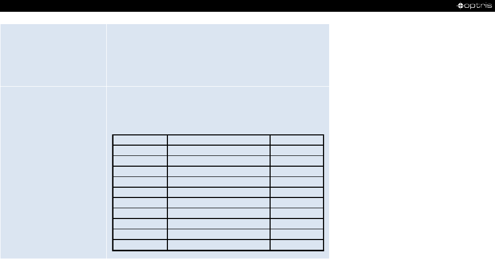
For a usage of the CS for online maintenance applications (in electrical cabinets e.g.) the following
recommend settings are already included in the factory default setting (but not active):
OUT
At 3-state output the following settings are default:
Pre-alarm difference: 2 °C
No alarm level: 8 V
Pre-alarm level: 5 V
Alarm level: 0 V
Service voltage: 10 V
-12 -
IN/ OUT
At Alarm output (open collector) the following settings are default:
Mode: normally closed
Temp code output: activated (for values above alarm level)
Range settings: 0 °C = 0 %/ 100 °C = 100 %
Vcc adjust
If activated the following settings are default:
Output voltage range: 0-10 V
Difference mode: activated
Alarm level Alarm value (IN/ OUT pin) Vcc
1 40 °C 11 V
2 45 °C 12 V
3 50 °C 13 V
4 55 °C 14 V
5 60 °C 15 V
6 65 °C 16 V
7 70 °C 17 V
8 75 °C 18 V
9 80 °C 19 V
10 85 °C 20 V

Technical Data 13-
2.2 General specifications
Environmental rating
IP63
Ambient temperature
-20...80 °C
Storage temperature
-40...85 °C
Relative humidity
10...95 %, non-condensing
Material
Stainless steel
Dimensions
85 mm, M12x1
Weight
58 g
Cable length
1 m (Standard), 3 m, 8 m, 15 m
Cable diameter
4.3 mm
Vibration
IEC 60068-2-6 (sinus shape), IEC 60068-2-64 (broad band noise)
Shock
IEC 60068-2-27 (25G and 50G)
-14 -
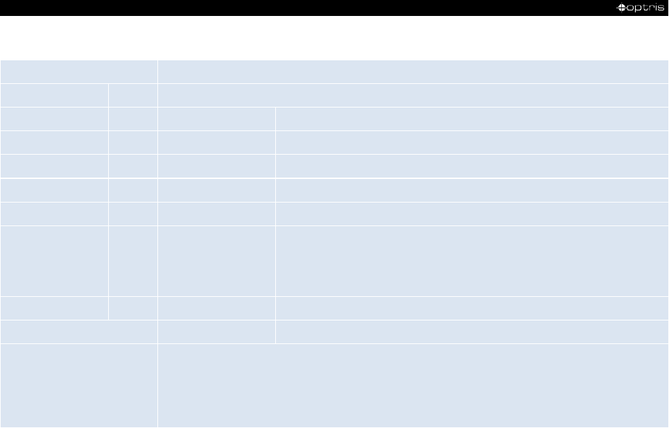
2.3 Electrical specifications
Used Pin
Function
OUT
IN/ OUT
x
Analog
0-5 V
1)
or 0-10 V
2)
/ scalable
x
Alarm
output voltage adjustable; N/O or N/C
x
Alarm
3-state alarm output (three voltage level for no alarm, pre-alarm, alarm)
x
Analog
programmable open collector output (NPN type) [0-30 V DC/ 50 mA]
4)
x
Temp. Code
Temp. Code Output (open collector (NPN type)) [0-30 V DC/ 50 mA]
4)
x
Input
programmable functions:
• external emissivity adjustment
• ambient temperature compensation
• triggered signal output and peak hold function
5)
x
x
Serial digital
3)
uni- (burst mode) or bidirectional
OUT t/c K
Analog
Thermocouple output type K; alternatively selectable to the mV output (software necessary)
Status LED
green LED with programmable functions:
• alarm indication (threshold independent from alarm outputs)
• automatic aiming support
• self-diagnostics
• temperature code indication
Technical Data 15-
Vcc adjust mode
10 adjustable emissivity and alarm values by variation of supply voltage/ Service mode for analog output
Output impedances
min. 10 kΩ load impedance
Current draw
10 mA
Power supply
5...30 VDC
6)
1)
0...4.6 V at supply voltage 5 VDC; also valid for alarm output
2)
only at supply voltage ≥ 11 V
3)
inverted RS232, TTL, 9.6 kBaud
4)
loadable up to 500 mA if the mV output is not used
5)
High level: > 0.8 V/ Low level: < 0.8 V
6)
The CS sensor may only be powered either via USB or externally, but not simultaneously!
1)
The t/c wires are indicated with an additional cable marker to avoid wrong connections due to the identical cable colors of other wires
(white, green).
Power supply [white]
Analog output/ TxD (5 V)/ Alarm output [yellow]
Analog input/ RxD (5 V)/ Open collector output [green]
Ground (⊥) [brown]
Thermocouple output type K (+) [green]
1)
Thermocouple output type K (-) [white]
1)
Shield [black]

-16 -
2.4 Measurement specifications
Temperature range
-50...1030 °C (scalable via Software)
Spectral range
8...14 µm
Optical resolution
15:1
CF-lens (optional)
0.8 mm@ 10 mm
Accuracy
1) 2)
±1.5 °C or ±1.5 % of reading (whichever is greater)
Repeatability
1)
±0.75 °C or ±0.75 % of reading (whichever is greater)
Temperature coefficient
3)
±0.05 K/ K or ±0.05 %/ K (whichever is greater)
Temperature resolution (NETD)
4)
50 mK
Response time
14 ms (90 % Signal/ adjustable to 999 s via Software)
Warm-up time
10 min
Emissivity/ Gain
0,100...1,100 (adjustable via 0-10 VDC input or software)
Transmissivity
0,100...1,000 (adjustable via software)
Interface (optional)
USB programming interface
Signal processing
Average, Peak hold, Valley hold, Advanced peak hold with threshold and
hysteresis, Triggered signal output, Triggered peak hold function (adjustable via
software)

Technical Data 17-
Software / App
optional (CompactConnect / IRmobile)
1)
at ambient temperature 23
5 °C and object temperatures >0 °C
2)
Accuracy for thermocouple output: ±2.5°C or ±1%
3)
for ambient temperatures <18 °C and >28 °C
4)
at time constant of 200 ms and an object temperature of 200 °C
2.5 Optical charts
• The size of the measuring object and the optical resolution of the infrared thermometer
determine the maximum distance between sensing head and measuring object.
• In order to prevent measuring errors the object should fill out the field of view of the optics
completely. Consequently, the spot should at all times have at least the same size like the
object or should be smaller than that.
The following optical charts show the diameter of the measuring spot in dependence on the distance
between measuring object and sensing head. The spot size refers to 90 % of the radiation energy.
The distance is always measured from the front edge of the sensing head.
-18 -
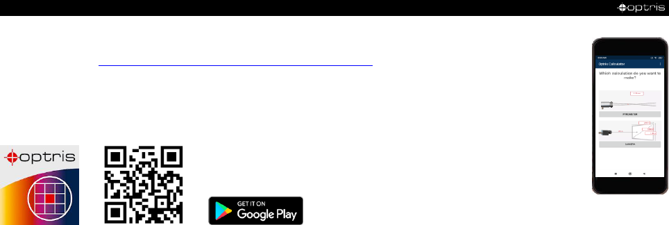
As an alternative to the optical diagrams, the spot size calculator can also be used on the
Optris website (https://www.optris.global/spot-size-calculator) or via the Optris calculator app.
The app can be downloaded for free from the Google Play store (see QR code).
D = Distance from front of the sensing
head to the object
S = Spot size
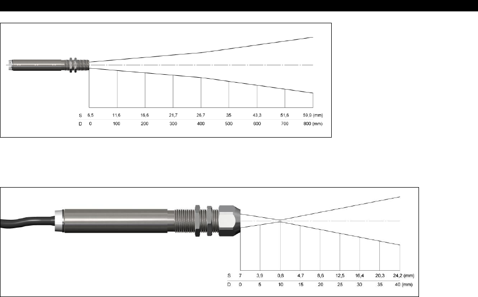
Technical Data 19-
Figure 1: Optical chart CS (15:1)
Figure 2: Optical chart CS (15:1) with CF-lens (0.8 mm@ 10 mm)
-20 -
2.6 Close focus optics
• If the CF-lens is used, the transmission has to be set to 0.78. To change this value the
optional USB-Kit (including software) is necessary.
• The assigned transmission (average value) is a characteristic value which may has a certain
scattering. If required the transmission has to be determined.
The optional CF-lens allows the measurement of small objects. The CF optics can also be combined with a
laminar air purge
Figure 3: CF-lens [Order-No.: ACCTCF]
Figure 4: Laminar air purge with integrated CF-lens
[Order-No.: ACCTAPLCF]

Technical Data 21-
2.7 LED-Functions
The green LED can be programmed for the following functions. For the programming the USB adapter
cable incl. software (option) is necessary. The factory default setting for the LED is self-diagnostic.
LED Alarm
LED lights up if the object temperature exceeds or deceeds an alarm threshold
Automatic aiming support
Sighting feature for an accurate aiming of the CS to hot or cold objects
Self-diagnostic
LED is indicating different states of the sensor
Temperature Code indication
Indication of the object temperature via the LED
Off
LED deactivated
2.7.1 Automatic aiming support
The automatic aiming support helps to adjust the unit to an object which has a temperature different to the
background. If this function is activated via software the sensor is looking for the highest object temperature;
means the threshold value for activating the LED will be automatically tuned.
This works also if the sensor is aimed at a new object (with probably colder temperature). After expiration of
a certain reset time (default setting: 10 s) the sensor will adjust the threshold level for activation of the LED
new.
-22 -
2.7.2 Self-diagnostic
At a supply voltage (Vcc) ≥ 12 V it takes about 5 minutes until the sensor works in a stable
mode. Therefore, after switching on the unit, the LED will show a not stable state for up to
5 minutes.
With this function the current status of the sensor will be indicated by different flash modes of the LED.
Figure 5: Sensor status
If activated, the LED will show one out of five possible states of
the sensor:
Status LED mode
Normal intermittent off - - - -
Sensor overheated fast flash - - - - - - - - - - - - -
Out of measuring range double flash -- -- -- -- -- -- --
Not stable intermittent on ––– ––– ––– –––
Alarm fault always on –––––––––––––––
Technical Data 23-
Sensor overheated
The internal temperature probes have detected an invalid high internal temperature of the CS.
Out of meas. range
The object temperature is out of measuring range.
Not stable
The internal temperature probes have detected an unequally internal temperature of the CS.
Alarm fault
Current through the switching transistor of the open-collector output is too high.
2.7.3 Temperature code indication
With this function the current measured object temperature will be indicated as percentage value by long and
short flashing of the LED. At a range setting of 0-100 °C → 0-100 % the LED flashing indicates the
temperature in °C.
Long flashing → first digit: xx
Short flashing → second digit: xx
10-times long flashing → first digit=0: 0x
10-times short flashing → second digit=0: x0

-24 -
Examples
87 °C 8-times long flashing indicates 87
and afterwards 7-times short flashing indicates 87
31 °C 3-times long flashing indicates 31
and afterwards 1-time short flashing indicates 31
8 °C 10-times long flashing indicates 08
and afterwards 8-times short flashing indicates 08
20 °C 2-times long flashing indicates 20
and afterwards 10-times short flashing indicates 20
Installation 25-
3 Installation
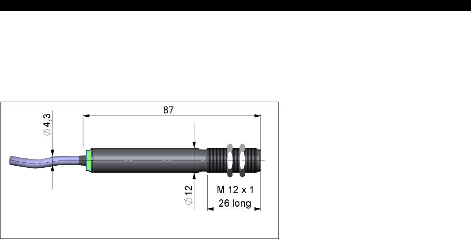
3.1 Mechanical Installation
The CS is equipped with a metric M12x1 thread and can be installed either directly via the sensor thread or
with the help of the both hex nuts (standard) to the mounting bracket available.
Figure 6: Dimensions CS
For an exact aiming of the sensor to an object the LED function ►2.7.1 Automatic aiming support can be
used.
-26 -
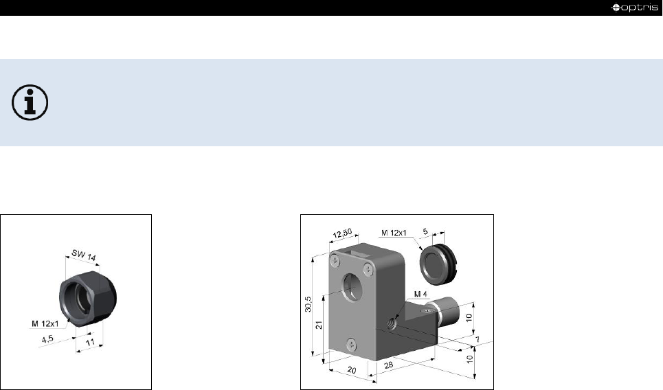
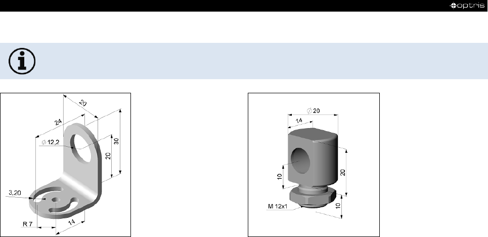
3.1.1 Mounting accessories
The Mounting fork can be combined with the Mounting bracket [Order No.: ACCTFB] using
the M12x1 thread.
Figure 7: Mounting bracket, adjustable in one axis
[Order No.: ACCTFB]
Figure 8: Mounting bolt with M12x1 thread, adjustable in
one axis [Order No.: ACCTMB]
Installation 27-
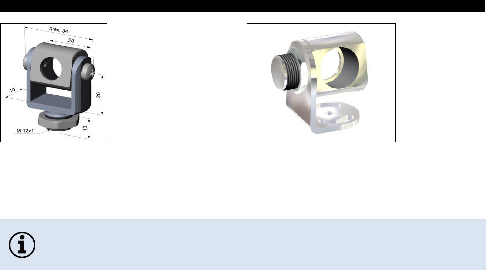
Figure 9: Mounting fork with M12x1 thread, adjustable in
2 axes [Order No.: ACCTMG]
Figure 10: Mounting bracket, adjustable in two axes
[Order No.: ACCTAB]
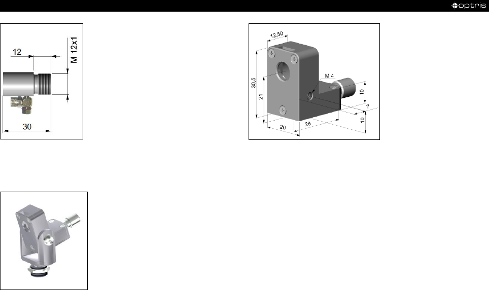
3.1.2 Air purge collar
• Use oil-free, technically clean air only.
• The needed amount of air (approx. 2...10 l/ min.) depends on the application and the
installation conditions on-site.
The lens must be kept clean at all times from dust, smoke, fumes and other contaminants in order to avoid
reading errors. These effects can be reduced by using an air purge collar.
-28 -
Figure 11: Standard air purge collar; fits to the mounting
bracket; hose connection: 3x5 mm [Order No.: ACCSAP]
Figure 12: Laminar air purge collar – the side air outlet
prevents a cooling down of the object in short distances;
hose connection: 3x5 mm [Order No.: ACCTAPL]
Figure 13: A combination of the laminar air purge collar with the bottom section of the mounting fork allows an
adjustment in two axes. [Order No.: ACCTAPL+ACCTMG]
Installation 29-
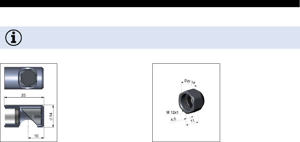
3.1.3 Other accessories
If the protective window is used, the transmission has to be set to 0.83. To change this value the
optional USB-Kit (including CompactConnect software) is necessary.
Figure 14: Right angle mirror enables measurement with
90° angle, for sensing heads with optical resolution ≥10:1
[Order No.: ACCTRAM]
Figure 15: Protective window same mechanical size as
CF lens [Order No.: ACCTPW]

-30 -
Figure 16: IR App Connector: USB adapter cable incl. terminal block [Order No.: ACCSMIAC]
3.1.4 Tilt assembly
With this mounting accessory a fine adjustment of the CS with an off-axis angle +/- 6.5° is possible.
Figure 17: Tilt assembly [Order No.: ACCTTAS]

Installation 31-
3.2 Electrical Installation
Use a separate, stabilized power supply unit with an output voltage in the range of 5–30 VDC
which can supply 100 mA. The residual ripple should be max 200 mV.
Note: The CS sensor may only be powered either via USB or externally, but not simultaneously!
• Use shielded cables only. The sensor shield has to be grounded.
• The shield [black] on the CS is not connected to GND [brown].In any case it is necessary to
connect the shield to ground or GND (whichever works best)!
• When using the thermocouple and an external power supply, there must be a connection
between ground and shield.
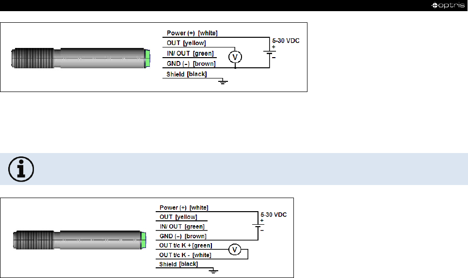
Analog device (mV-output at OUT pin)
The output impedance must be ≥ 10 kΩ.
-32 -
Figure 18: Analog device (mV output at OUT pin)
Analog device (Thermocouple typ K at OUT t/c K pins)
The output impedance must be ≥ 20 kΩ.
Figure 19: Analog device (Thermocouple typ K at OUT t/c K pins)
Installation 33-
You can choose between an mV output (0-5 or 0-10 V; scalable via software) and a thermocouple output
type K. Therefor the optional software is needed. The factory default setting is mV output.
►2.1 Default settings
The thermocouple output supplies a voltage according to the t/c characteristic curve type K. If you want to
extend this output you have to use a suitable thermocouple extension cable (NiCr-Ni).
3.2.1 Digital communication
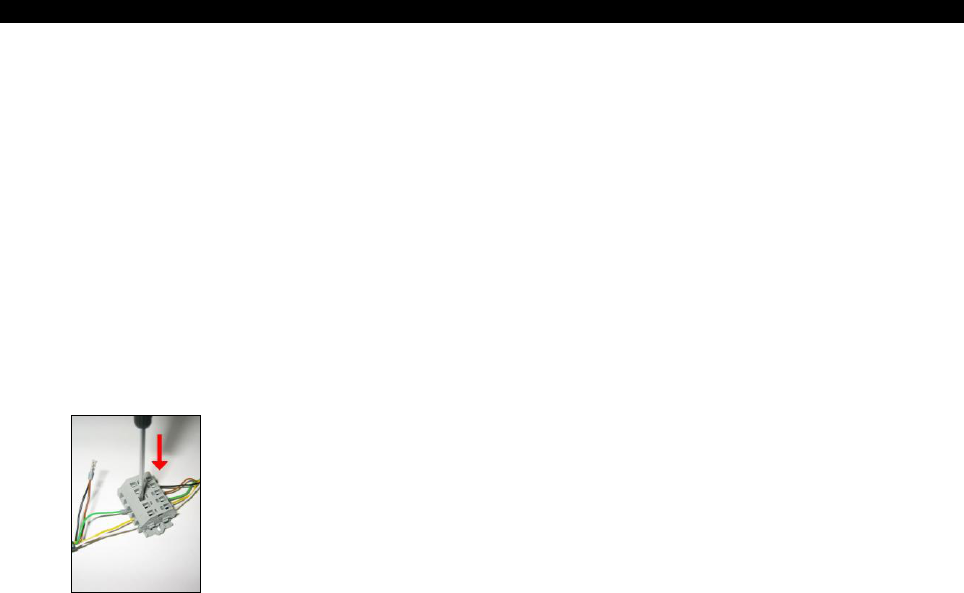
For a digital communication the optional USB programming kit is required.
1. Connect each wire of the USB adapter cable with the same colored wire of the sensor cable by using
the terminal block. Press with a screw driver as shown in the picture to lose a contact.
Figure 20: Connection USB cable
-34 -
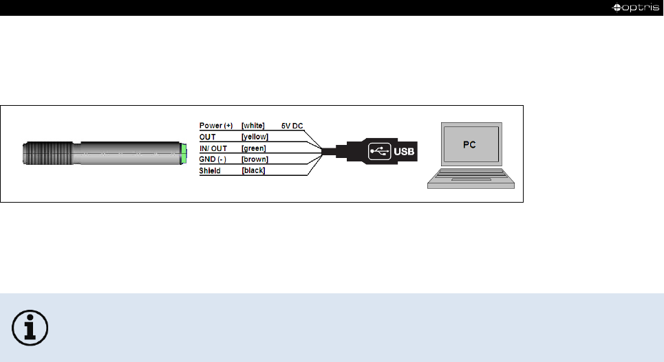
The sensor is offering two ways of digital communication:
• bidirectional communication (sending and receiving data)
• unidirectional communication (burst mode – the sensor is sending data only)
Figure 21: Digital communication
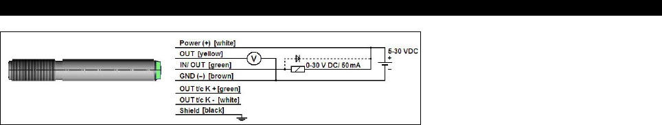
3.2.2 Open collector output
In case of long lines there is a drop voltage at the ground wire and the mV-output is distorted.
Because of that the brown wire can be used as ground supply and the t/c- wire (type K) as
measuring ground.
Installation 35-
Figure 22: Open collector output as additional alarm output
The open collector output is an additional alarm output on the CS and can control an external relay e.g. In
addition the analogue output can be used simultaneously.
3.2.3 Direct connection to a RS232 on the computer
For a bidirectional RS232 connection of the sensor the following interface circuit can be used: MAX3381E
(manufacturer: Maxim) ► Appendix C – Direct connection to a RS232 interface:
-36 -
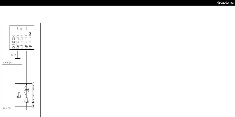
4 Schematic circuit diagrams for maintenance applications
Figure 23: Open collector output for direct 24 V DC signal lamp control
Schematic circuit diagrams for maintenance applications 37-
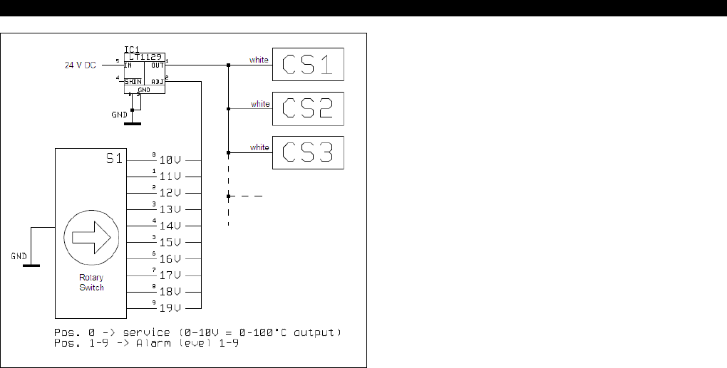
Figure 24: Common power supply voltage change to adjust simultaneously alarm levels and emissivity values
[Vcc adjust mode]
-38 -
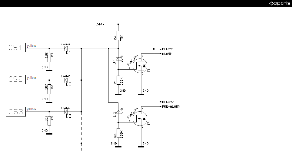
Figure 25: Simple common alarm and pre-alarm generation

IRmobile app 39-
5 IRmobile app
The CS sensor has a direct connection to an Android smartphone or tablet. All you have to
do is download the IRmobile app for free in the Google Play store. This can also be done
via the QR code. An IR app connector is required for connection to the device (Part-No.:
ACCSMIAC).
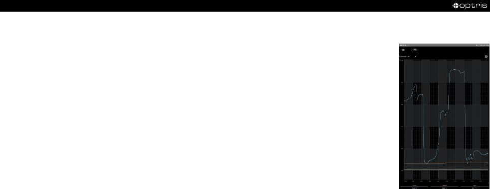
With IRmobile you are able to monitor and analyse your infrared temperature measurement on a connected
smartphone or tablet. This app works on most Android devices running 5.0 or higher with a micro USB or
USB-C port supporting USB-OTG (On The Go). It is easy to operate: after you plug your CS device to your
phone or tablet, the app will start automatically. The device is powered by your phone. Different digital
temperature values can be displayed in the temperature time diagram. You can easily zoom-in the diagram
to see more details and small signal changes.
-40 -
IRmobile app features:
➢ Temperature time diagram with zoom function
➢ Digital temperature values
➢ Setup of emissivity, transmissivity and other parameters
➢ Scaling of the analog output and setting of the alarm output
➢ Change of temperature unit: Celsius or Fahrenheit
➢ Saving/loading of configurations and T/t diagrams
➢ Restore factory default sensor settings
➢ Integrated simulator
Supported for:
➢ Optris pyrometers: Compact series, high performance series and video thermometers
➢ Optris IR cameras: PI and Xi series
➢ For android devices running 5.0 or higher with a micro USB or USB-C port supporting USB-OTG (On
The Go)

Software CompactConnect 41-
6 Software CompactConnect
Minimum system requirements:
• Windows 7, Windows 8, Windows 10
• USB interface
• Hard disc with at least 30 MByte of free space
• At least 128 MByte RAM
• A detailed description is provided in the software manual on the downloaded software
package.
• The software only supports USB cables ordered directly from Optris.
6.1 Installation
The software can be downloaded under https://www.optris.global/downloads-software. Unzip and open the
program and start the CDsetup.exe. Follow the instructions of the wizard until the installation is finished.
The installation wizard will place a launch icon on the desktop and in the start menu:
[Start]\Programs\CompactConnect.
If you want to uninstall the software from your system please use the uninstall icon in the start menu.
-42 -
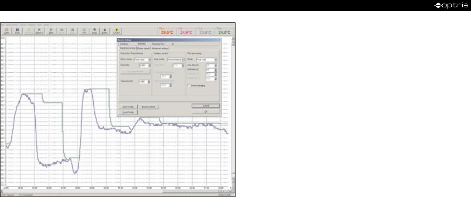
Figure 26: Software CompactConnect
Main functions:
• Graphic display for temperature trends
and automatic data logging for analysis
and documentation
• Complete sensor setup and remote
controlling
• Adjustment of signal processing
functions
• Programming of outputs and functional
inputs
Software CompactConnect 43-
6.2 Communication settings
For further information see protocol and command description on the software package
CompactConnect in the directory: \Commands.
6.2.1 Serial Interface
Baud rate:
9,6 / 115,2 kBaud (adjustable via software)
Data bits:
8
Parity:
none
Stop bits:
1
Flow control
off
6.2.2 Protocol
All sensors of the CS series are using a binary protocol. To get a fast communication the protocol has no
additional overhead with CR, LR or ACK bytes. To power the sensor the control signal „DTR“ has to be set.

-44 -
7 Basics of Infrared Thermometry
Depending on the temperature each object emits a certain amount of infrared radiation. A change in the
temperature of the object is accompanied by a change in the intensity of the radiation. For the measurement
of “thermal radiation” infrared thermometry uses a wave-length ranging between 1 µm and 20 µm. The
intensity of the emitted radiation depends on the material. This material contingent constant is described with
the help of the emissivity which is a known value for most materials (►8 Emissivity).
Infrared thermometers are optoelectronic sensors. They calculate the surface temperature on the basis of
the emitted infrared radiation from an object. The most important feature of infrared thermometers is that
they enable the user to measure objects contactless. Consequently, these products help to measure the
temperature of inaccessible or moving objects without difficulties. Infrared thermometers basically consist of
the following components:
• lens
• spectral filter
• detector
• electronics (amplifier/ linearization/ signal processing)
The specifications of the lens decisively determine the optical path of the infrared thermometer, which is
characterized by the ratio Distance to Spot size. The spectral filter selects the wavelength range, which is
relevant for the temperature measurement. The detector in cooperation with the processing electronics
transforms the emitted infrared radiation into electrical signals.

Emissivity 45-
8 Emissivity
8.1 Definition
The intensity of infrared radiation, which is emitted by each body, depends on the temperature as well as on
the radiation features of the surface material of the measuring object. The emissivity (ε – Epsilon) is used as
a material constant factor to describe the ability of the body to emit infrared energy. It can range between 0
and 100 %. A “blackbody” is the ideal radiation source with an emissivity of 1.0 whereas a mirror shows an
emissivity of 0.1.
If the emissivity chosen is too high, the infrared thermometer may display a temperature value which is much
lower than the real temperature – assuming the measuring object is warmer than its surroundings. A low
emissivity (reflective surfaces) carries the risk of inaccurate measuring results by interfering infrared radiation
emitted by background objects (flames, heating systems, chamottes). To minimize measuring errors in such
cases, the handling should be performed very carefully and the unit should be protected against reflecting
radiation sources.

-46 -
8.2 Determination of unknown emissivity
► First determine the actual temperature of the measuring object with a thermocouple or contact sensor.
Second, measure the temperature with the infrared thermometer and modify the emissivity until the
displayed result corresponds to the actual temperature.
► If you monitor temperatures of up to 380 °C you may place a special plastic sticker (emissivity dots –
Order No.: ACLSED) onto the measuring object, which covers it completely. Set the emissivity to 0.95
and take the temperature of the sticker. Afterwards, determine the temperature of the adjacent area on
the measuring object and adjust the emissivity according to the value of the temperature of the sticker.
► Cove a part of the surface of the measuring object with a black, flat paint with an emissivity of 0.98. Adjust
the emissivity of your infrared thermometer to 0.98 and take the temperature of the colored surface.
Afterwards, determine the temperature of a directly adjacent area and modify the emissivity until the
measured value corresponds to the temperature of the colored surface.
CAUTION: On all three methods the object temperature must be different from ambient temperature.

Emissivity 47-
8.3 Characteristic emissivity
In case none of the methods mentioned above help to determine the emissivity you may use the emissivity
table ► Appendix A and Appendix B. These are average values, only. The actual emissivity of a material
depends on the following factors:
• temperature
• measuring angle
• geometry of the surface
• thickness of the material
• constitution of the surface (polished, oxidized, rough, sandblast)
• spectral range of the measurement
• transmissivity (e.g. with thin films)
-48 -
Appendix A – Table of emissivity for metals
typical
Emissivity
typical
Emissivity
Aluminium non oxidized 0,02-0,1 Lead roughened 0,4
polished 0,02-0,1 oxidized 0,2-0,6
roughened 0,1-0,3 Magnesium 0,02-0,1
oxidized 0,2-0,4 Mercury 0,05-0,15
Brass polished 0,01-0,05 Molybdenum non oxidized 0,1
roughened 0,3 oxidized 0,2-0,6
oxidized 0,5 Monel (Ni-Cu) 0,1-0,14
Copper polished 0,03 Nickel electrolytic 0,05-0,15
roughened 0,05-0,1 oxidized 0,2-0,5
oxidized 0,4-0,8 Platinum black 0,9
Chrome 0,02-0,2 Silver 0,02
Gold 0,01-0,1 Steel polished plate 0,1
Haynes alloy 0,3-0,8 rustless 0,1-0,8
Inconel electro polished 0,15 heavy plate 0,4-0,6
sandblast 0,3-0,6 cold-rolled 0,7-0,9
oxidized 0,7-0,95 oxidized 0,7-0,9
Iron non oxidized 0,05-0,2 Tin non oxidized 0,05
rusted 0,5-0,7 Titanium polished 0,05-0,2
oxidized 0,5-0,9 oxidized 0,5-0,6
forged, blunt 0,9 Wolfram polished 0,03-0,1
Iron, casted non oxidized 0,2 Zinc polished 0,02
oxidized 0,6-0,95 oxidized 0,1
Lead polished 0,05-0,1
Material
Material

Appendix B - Table of emissivity for non-metals 49-
Appendix B - Table of emissivity for non-metals
1,0 µm 2,2 µm 5,1 µm 8-14 µm
Asbestos 0,9 0,8 0,9 0,95
Asphalt 0,95 0,95
Basalt 0,7 0,7
Carbon non oxidized 0,8-0,9 0,8-0,9 0,8-0,9
graphite 0,8-0,9 0,7-0,9 0,7-0,8
Carborundum 0,95 0,9 0,9
Ceramic 0,4 0,8-0,95 0,8-0,95 0,95
Concrete 0,65 0,9 0,9 0,95
Glass plate 0,2 0,98 0,85
melt 0,4-0,9 0,9
Grit 0,95 0,95
Gypsum 0,4-0,97 0,8-0,95
Ice 0,98
Limestone 0,4-0,98 0,98
Paint non alkaline 0,9-0,95
Paper any color 0,95 0,95
Plastic >50 µm non transparent 0,95 0,95
Rubber 0,9 0,95
Sand 0,9 0,9
Snow 0,9
Soil 0,9-0,98
Textiles 0,95 0,95
Water 0,93
Wood natural 0,9-0,95 0,9-0,95
Material
typical Emissivity
Spectral response
-50 -
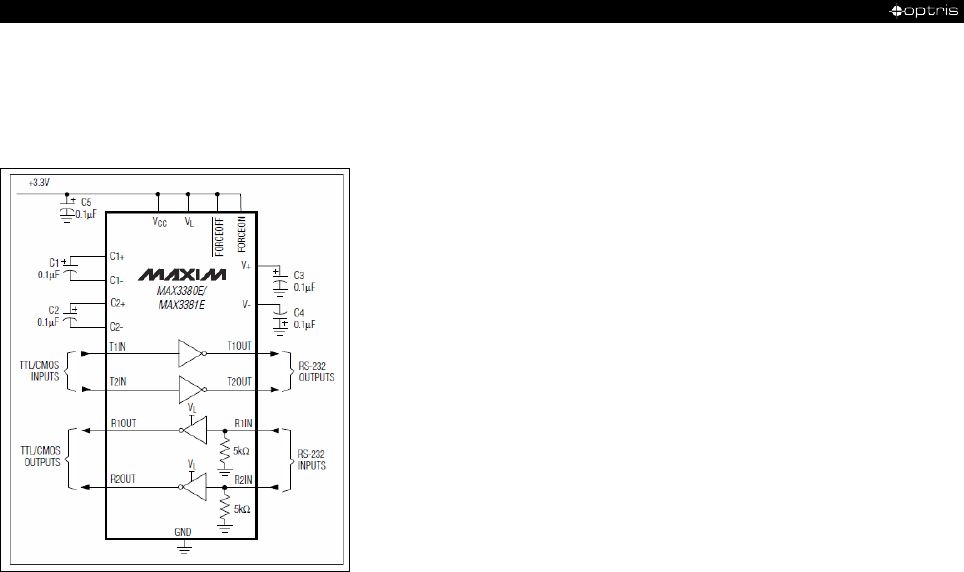
Appendix C – Direct connection to a RS232 interface
For a bidirectional RS232 connection of the sensor we recommend the interface circuit from Maxim, e.g.
MAX3381E.

Appendix C – Direct connection to a RS232 interface 51-
Model
CSv1
CSv2
CSv3
UART voltage (RxD)
5 V
3,3 V
3,3 V
UART voltage (TxD)
5 V
3,3 V
3,3 V
Previous sensor versions:
CSv1 CS/ version 1 (→ 12/2010)
CS connections:
TxD (yellow) an T1IN
RxD (green) an R1OUT
GND (brown) an GND
PC connections:
connect T1OUT with RxD (PC)
connect R1IN with TxD (PC)
-52 -
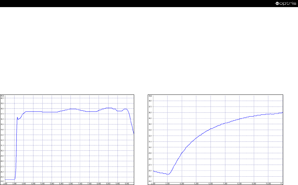
Appendix D – Smart Averaging
The average function is generally used to smoothen the output signal. With the adjustable parameter time
this function can be optimal adjusted to the respective application. One disadvantage of the average function
is that fast temperature peaks which are caused by dynamic events are subjected to the same averaging
time. Therefore those peaks can only be seen with a delay on the signal output.
The function Smart Averaging eliminates this disadvantage by passing those fast events without averaging
directly through to the signal output.
Signal graph with Smart Averaging function Signal graph without Smart Averaging function
Appendix E – Declaration of Conformity 53-
Appendix E – Declaration of Conformity
optris CS
-MA-E2020-10-A
